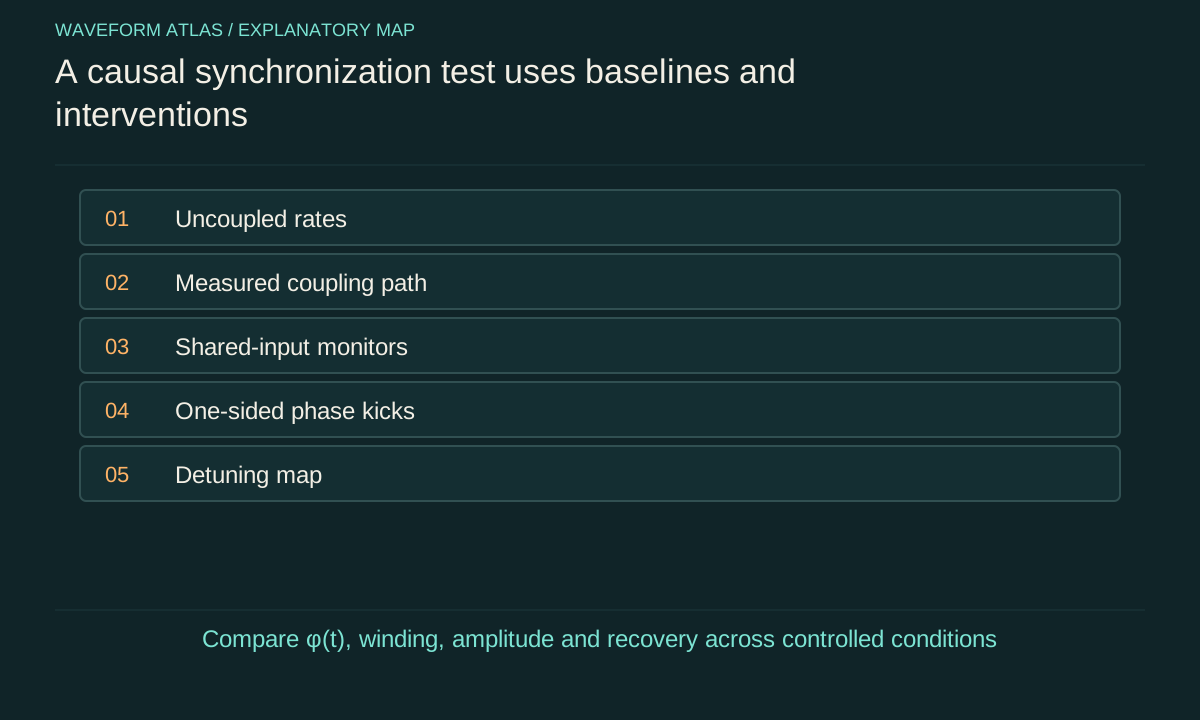
Write the causal claim before recording traces
Decide whether the experiment tests mutual synchronization, one-way entrainment or coordination under a common drive. These are different causal arrangements even when their final waveforms look similar. Identify the physical coupling path and the energy source maintaining each oscillator. Define the expected frequency ratio, phase relation and observation duration before selecting a statistic.
For a mechanical demonstration, two self-sustained oscillators on a movable support provide one possible interaction path. For an electronic setup, a calibrated coupling circuit may provide another. The apparatus should allow that path to be varied or interrupted while keeping unrelated operating conditions as steady as possible. A visually convincing pair of traces is a useful observation, but it is not yet a controlled test of the claimed interaction.
Establish uncoupled behavior
Record each oscillator with its sustaining mechanism active and the intended coupling absent or minimized. Estimate its mean frequency, amplitude variability and phase noise over a duration relevant to the later locking test. Repeat to identify slow drift. Two oscillators that happen to have almost equal rates can look coordinated for a short interval even without interaction.
Keep the reference conditions comparable. Removing a platform connection can change mechanical loading; unplugging an electrical path can change impedance. Use a matched or characterized control when possible, and document unavoidable changes. Otherwise, a frequency shift after coupling is introduced may reflect altered individual dynamics rather than the phase interaction the experiment intends to study.
Extract phases without inventing slips
For clean cycles, one phase convention assigns θ=2πn at each chosen landmark and interpolates between consecutive landmarks. An analytic-signal method can provide another estimate when its assumptions fit the waveform. State the method, filtering and treatment of missing or distorted cycles. The phase should correspond to the physical oscillation, not merely to whatever component a filter selects.
Compare extracted phases with raw traces around apparent jumps. Low amplitude, overlapping harmonics or sensor noise can make a phase estimate unreliable. Unwrap angles to preserve full-cycle drift, and retain timestamps from a common calibrated acquisition clock. Synchronized acquisition is useful; leakage of the same electronic reference into both measured channels is a different issue that needs an independent cross-talk check.
Define a locking criterion and its resolution
For one-to-one locking, inspect φ=θ₁−θ₂. For a p:q ratio, use qθ₁−pθ₂ with the convention stated. A practical criterion can combine a localized phase distribution, small mean winding rate and a specified slip limit over the observation interval. Report the interval and measurement uncertainty rather than treating a finite trace as proof of permanent exact locking.
Frequency estimates should be compared with the phase record. A small mean difference can hide opposite slips that cancel over the full run, while a short record can miss a slow persistent drift. Inspect several window lengths and repeat trials. The result should distinguish stable coordination, intermittent locking and unresolved slow drift instead of compressing all three into one yes-or-no label.
Sweep detuning and coupling
Change the free-running mismatch and interaction strength while recording phases and amplitudes. A simple phase model predicts a locking region and a preferred offset that varies with detuning. Test both, not only whether frequencies become equal. Use consistent dwell times and allow longer settling near boundaries where restoring dynamics can become slow.
Randomize or interleave settings when drift could bias a sequential sweep. Measure the actual physical coupling parameter rather than assuming a control voltage is proportional to effective phase coupling. A map that follows a model across multiple conditions provides stronger evidence than a single favorable operating point. Disagreements can reveal amplitude effects, delayed interaction or an incorrect coupling function.
Perturb one oscillator at a time
Apply a small controlled phase disturbance to oscillator one and observe both systems. Repeat for oscillator two. In a mutually coupled pair, both can adjust; in a one-way arrangement, the driver should remain approximately unaffected while the follower recovers. Compare the direction and time scale of adjustment with the proposed model.
The perturbation itself can enter the shared environment, so repeat with the intended coupling weakened or blocked. A response that persists through an unintended path needs to be included in the causal account. Also distinguish phase and amplitude kicks: an immediate displacement change may relax without a lasting timing shift. The test should measure recovery after the relevant amplitude transient has been understood.
Test common forcing and noise alternatives
Remove or alter a shared periodic reference while preserving each oscillator's sustaining energy supply. If the pair remains coordinated only when that reference is present, the result may be common-drive entrainment. If a shared noisy input is suspected, compare correlated and independent perturbations under controlled conditions. Common-noise theory shows why direct coupling is not the only route to phase coordination.
These alternatives are not failures of the experiment; they are different mechanisms. The report should name the one supported by the controls. A useful negative control can replace a coupling path with a matched load that preserves loading but removes information transfer. Where that is impossible, state the limitation and avoid claiming that one intervention uniquely isolated the intended interaction.
A matched-load control is especially useful in an electronic experiment. Disconnecting a coupling cable can change an oscillator's impedance and therefore its free-running frequency. Replacing the receiving path with a characterized load can preserve much of that loading while removing the intended information-bearing feedback. The control is imperfect if the real load is dynamic, so measure the remaining difference rather than assuming the replacement is exact.
An analogous mechanical control might constrain support motion while preserving mass and mounting as closely as possible. That intervention also changes boundary conditions, which must be included in the comparison. There is no universal way to turn coupling off without affecting anything else; the goal is to make the intervention's consequences measurable and modelable.
Run a sensor cross-talk check by driving or moving only one system while the other is physically quiet. A copied signal in the second measurement channel can create an apparent phase relation even when the second oscillator contributes little. Independent sensing or a changed readout geometry can test that artifact. These controls establish that the recorded coordination belongs to the physical systems rather than to their measurement wiring or image-processing pipeline.
Fit dynamics and check predictions
A phase model such as φ̇=Δ−Ksinφ can be tested through phase offsets, recovery rates and drift outside the locking region. Estimating derivatives directly from noisy phase data can amplify measurement noise, so use a suitable time-increment or state-space method and include uncertainty. Check the model on conditions not used to determine its parameters.
Inspect residuals and amplitude dependence. If the same parameters cannot explain both steady offsets and perturbation recovery, the model may omit amplitude dynamics or a delayed mediator. A good fit to one histogram is not enough to establish the full causal mechanism. Combining several independent predictions makes the interpretation more robust and reveals where a reduced phase description stops being adequate.
For example, a phase model fitted only to the stationary offset determines the ratio Δ/K, not both parameters independently. An uncoupled frequency measurement constrains Δ, while a small-perturbation recovery rate supplies another relation through √(K²−Δ²). Combining them tests whether one K explains both equilibrium and dynamics. This is a more discriminating identification procedure than fitting the offset alone.
If the inferred K changes with perturbation size, the linear recovery approximation may have failed or amplitude effects may matter. Use a range of small kicks and verify convergence toward a consistent local rate. Large perturbations can still be useful for mapping basins and robustness, but they answer a different question and should not be mixed into a small-signal stability estimate without an appropriate nonlinear model.
Report a reproducible coordination result
Include raw representative traces, the phase definition, uncoupled frequency estimates, coupling controls, parameter map, perturbation response and uncertainty. State the number and duration of trials and whether slips or alternative stable states occurred. Keep synchronization metrics separate from power, deformation or quantum-state claims unless those were measured independently.
The strongest conclusion is specific: under these conditions, this interaction stabilizes this timing relation, with this recovery and reliability. Such a result can be reproduced and challenged by changing the relevant parameters. It is more informative than a video of apparently aligned motion because the controls explain why the coordination occurs and distinguish it from coincidence, a shared source or a measurement artifact.
What to take forward
- Measure uncoupled rhythms and the physical coupling path.
- Use one-sided perturbations and common-input controls to identify directionality.
- A locking map and recovery prediction provide stronger evidence than similar traces.
Go to the original work.
These links identify the sources behind specific claims. Verification scope varies by source and is stated below.
- 1 / Primary theoryHuygens’ Synchronization: Experiments, Modeling, and Local Stability Analysis ↗
F. N. Hoogeboom; A. Y. Pogromsky; H. Nijmeijer. IFAC-PapersOnLine 48(18), 146–151 (2015).
DOI: 10.1016/j.ifacol.2015.11.027
Platform parameters affect the stability of in-phase and antiphase metronome states.
Verification scope: Publisher or author-institution abstract and bibliographic record inspected; full paper not audited.
- 2 / Primary theoryA Study of Locking Phenomena in Oscillators ↗
Robert Adler. Proceedings of the IRE 34(6), 351–357 (1946).
DOI: 10.1109/JRPROC.1946.229930
A reduced phase equation describes injection locking and phase drift under specified oscillator assumptions.
Verification scope: Publisher or author-institution abstract and bibliographic record inspected; full paper not audited.
- 3 / Primary theoryRobustness of the Noise-Induced Phase Synchronization in a General Class of Limit Cycle Oscillators ↗
Jun-nosuke Teramae; Dan Tanaka. Physical Review Letters 93, 204103 (2004).
DOI: 10.1103/PhysRevLett.93.204103
Common weak additive noise can synchronize a specified class of otherwise uncoupled limit-cycle oscillators.
Verification scope: Publisher or author-institution abstract and bibliographic record inspected; full paper not audited.
Found a problem with a claim or calculation? Send the page, the claim and the evidence. Read how these articles were prepared.