The return path completes the system
An amplifier by itself is not the whole dynamical system when output can return to input. Cables, reflections, acoustic paths, optical cavities, and electronic feedback networks can all form loops. Their frequency-dependent magnitude and phase determine whether returned disturbances reinforce or oppose the next response.
A microphone and loudspeaker provide a familiar example. Sound emitted by the speaker reaches the microphone, is amplified again, and can circulate repeatedly. The acoustic travel time, room response, microphone sensitivity, and amplifier response all matter. A similar principle applies to optical feedback and microwave reflections, though the detailed modes differ. The supply or pump powers any sustained growth. A loop does not create energy; it provides a route by which supplied energy can be organized into a growing disturbance. Stability analysis must therefore include the return path and its delay.
A simple loop equation shows the danger
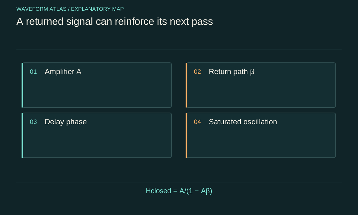
Let an amplifier response be A(s) and a feedback path be β(s). For one positive-feedback sign convention, the closed-loop response is A(s)/[1−A(s)β(s)]. The product L(s) = A(s)β(s) is loop gain. Frequencies near a condition where the denominator becomes small can show a large response, but full stability depends on the locations of the closed-loop poles.
The familiar magnitude-one and reinforcing-phase condition is useful intuition for an oscillation threshold in suitable systems. It is not a universal substitute for a complete stability test, especially with multiple poles, delays, or open-loop unstable dynamics. Sign conventions also change whether the critical phase is described as zero or minus 180 degrees. State the feedback equation before quoting a phase criterion. Otherwise two correct descriptions can appear contradictory simply because one defines the feedback sign differently.
Delay rotates the returned phase
A pure time delay τ contributes a frequency-dependent phase factor exp(−iωτ). Even if the feedback is opposing at low frequency, increasing phase lag can make it reinforcing elsewhere. A long cable or acoustic path therefore changes the loop's stability without necessarily changing its low-frequency amplitude gain.
For an illustrative delay of 1 millisecond, the delay alone contributes a full 360-degree phase rotation at 1 kilohertz and 180 degrees at 500 hertz. Other amplifier and filter phases must be added before identifying an unstable mode. This calculation explains why moving a microphone, changing a cable length, or adding a filter can alter a feedback tone. The observed oscillation frequency is selected by the combined loop response, not necessarily by the frequency of the last external signal applied to the amplifier.
Growth rate is a dynamical quantity
Near an instability, a mode can behave approximately as a(t) = a0 exp[(r+iω)t], where r is a growth or decay rate. Positive r means a small disturbance grows; negative r means it relaxes. The initial disturbance can be thermal noise, quantum noise, a switching transient, or an external signal. Its origin affects the initial phase and statistics, but not the fact that sustained growth requires supplied energy.
For an illustrative r = 100 inverse seconds, amplitude doubles in ln(2)/r ≈ 6.93 milliseconds within the linear growth regime. Energy proportional to amplitude squared grows faster. That exponential cannot continue indefinitely in a real device. As amplitude rises, gain compression, pump depletion, heating, or another nonlinearity changes the dynamics. The early growth rate and final oscillation amplitude are therefore different measurements requiring different parts of the model.
Saturation produces a finite oscillation
A simple amplitude model can write da/dt = (r−s|a|²)a with positive s. For r > 0, the zero-amplitude state is unstable and a nonzero steady magnitude √(r/s) can appear in this idealized model. The nonlinear term represents gain reduction or another amplitude-limiting process. It is a phenomenological example, not a universal equation for every oscillator.
The phase may remain free in an ideal autonomous oscillator and then wander under noise, while an injected signal can lock it under suitable conditions. More complicated nonlinearities can produce multiple modes, hysteresis, quasiperiodic motion, or chaotic behavior. A stable-looking tone is therefore only one possible post-threshold outcome. To interpret it, measure frequency, amplitude, linewidth, and their dependence on pump or gain setting. The limiting mechanism should be tied to observed compression or device physics rather than assumed from the existence of a finite output.
A laser is a useful optical example
A laser combines gain with feedback so that certain optical modes can sustain oscillation. At threshold, the round-trip amplification and losses balance for an allowed mode. Above threshold, gain saturation and mode competition shape the steady output. The pump supplies the emitted energy.
An optical amplifier can accidentally acquire enough feedback from reflections to lase or develop narrow spectral features. The output may then persist even without the intended input signal. Measuring that output as though it were entirely amplified signal overstates the device's response. Changing mirror alignment, isolation, or return-path loss can reveal the feedback origin. The general lesson is that stable amplification and autonomous oscillation are distinct operating regimes. A device can move between them as gain, loss, phase, or boundary conditions change, even if its physical components remain the same.
Noise and coherence change near threshold
Below threshold, a stable amplifier can strongly enhance fluctuations near a resonance. As damping becomes small, the response narrows and the correlation time grows in a simple linear model. Above threshold, a macroscopic oscillation can emerge, but its phase and amplitude still fluctuate. A narrow spectral peak does not imply perfectly deterministic phase for unlimited time.
Quantum and thermal noise can seed an oscillator without supplying its macroscopic energy. The pump or supply provides that energy as the seed is amplified. This distinction prevents a misleading story in which vacuum fluctuations become a free fuel source. Noise statistics and phase diffusion require a model of the oscillator and measurement. A claim that feedback creates greater coherence should specify a measurable quantity such as linewidth or phase correlation, rather than infer it solely from a stronger peak in a spectrum.
Stable feedback can also be useful
Feedback is not inherently destabilizing. Properly designed negative feedback can reduce sensitivity to component variation, shape bandwidth, suppress disturbances, or improve linearity over a specified range. Those benefits depend on maintaining adequate stability margins and respecting delay, noise, and actuator limits.
A controller can also shift where noise appears in the measured system. An in-loop error signal may be small because the loop correlates measurement noise with the physical response. An independent out-of-loop sensor provides a stronger test of actual suppression at the application point. Large transients can saturate an actuator and invalidate a small-signal stability analysis, so both linear response and nonlinear operating limits matter. The useful design question is how the complete loop behaves over expected disturbances and parameter changes, not whether feedback is present in the abstract.
A practical instability diagnosis
Measure the response with the intended loop configuration and, where feasible, with the return path reduced or interrupted in a controlled way. Vary delay, termination, gain, or coupling one parameter at a time. A tone that shifts with return-path length or disappears when feedback is reduced supports a loop mechanism.
Check the spectrum with no intended input and compare it with the driven response. Monitor pump or supply conditions and confirm that the detector is not generating or aliasing a spurious tone. Time-domain records can reveal exponential startup, saturation, beating, or intermittent bursts that an averaged spectrum hides. A complete report should identify the threshold procedure and whether hysteresis occurs. The diagnosis is stronger when a measured loop or transfer model predicts the observed frequency and growth trend rather than merely explaining them after the fact.
Do not label every growing wave an amplifier output
A growing mode can be an instability of a coupled system, a transient response, or a deliberately driven signal. These possibilities differ in what determines phase, frequency, and information content. A self-oscillator can produce a large output unrelated to an external input waveform, while a stable amplifier aims to preserve a controlled relation to that input.
The final description should state the regime and the energy source. If a loop sustains oscillation, report its threshold, limiting mechanism, and noise rather than presenting the result as unlimited gain. If the system remains stable, characterize its gain and margins over the intended band. Feedback instability is an ordinary dynamical route from small fluctuations to large motion; it does not establish wave collapse, energy creation, or a universal rule that any sufficiently amplified wave must disappear.
A feedback threshold can shift as the device warms because gain and phase both change. Measuring only the cold startup can therefore miss an instability that appears later. A useful endurance test monitors the no-signal spectrum after thermal settling and during representative load changes, with the same terminations and cables used in the intended application.
What to take forward
- Stability depends on the complete frequency-dependent loop, including delay.
- Noise can seed growth, but the supply or pump provides its energy.
- Self-oscillation is a different regime from faithful amplification of an external signal.
Go to the original work.
These links identify the sources behind specific claims. Verification scope varies by source and is stated below.
- 1 / University teachingSignals and Systems — Alan V. Oppenheim, lecture notes ↗
Alan V. Oppenheim. Signals and Systems — Alan V. Oppenheim, lecture notes. 2011.
Convolution, linear systems, filtering and feedback
Verification scope: Official course notes and topic records inspected
- 2 / University teachingFundamentals of Photonics: Quantum Electronics — lecture notes ↗
Franz X. Kärtner. Fundamentals of Photonics: Quantum Electronics — lecture notes. 2006.
Population dynamics, absorption/gain, Rabi oscillations and coupled modes
Verification scope: Official author-written course materials and topic mapping inspected
- 3 / University teachingWave Propagation — Triantaphyllos Akylas, lecture notes ↗
Triantaphyllos Akylas. Wave Propagation — Triantaphyllos Akylas, lecture notes. 2017.
Transient wave propagation, elastic modes, interfaces and water waves
Verification scope: Official chapter contents and author-written course records inspected
- 4 / University teachingQuantum Optical Communication — Jeffrey H. Shapiro, readings and lecture slides ↗
Jeffrey H. Shapiro. Quantum Optical Communication — Jeffrey H. Shapiro, readings and lecture slides. 2016.
Author-written quantum attenuator, amplifier, detection and parametric interaction framework
Verification scope: Official course materials and topic mapping inspected
- 5 / Primary researchQuantum limits on noise in linear amplifiers ↗
C. M. Caves. Physical Review D 26(8), 1817 (1982).
Deterministic linear-amplifier quantum-noise limits, with distinct phase-insensitive and phase-sensitive tasks.
Verification scope: Publisher record and abstract, author-paper first-page excerpt inspected
- 6 / Primary researchLow-noise cryogenic microwave amplifier characterization with a calibrated noise source ↗
M. Malnou; T. F. Q. Larson; J. D. Teufel; F. Lecocq; J. Aumentado. Review of Scientific Instruments 95(3), 034703 (2024). Linked record is the author preprint.
Noise reference planes, attenuation and Friis relations, Y-factor fitting, signal/idler inputs, parametric gain, saturation, and spectral-density units.
Verification scope: Relevant author-preprint full text (§§II.1–II.6 and Appendix D) inspected; published 2024 metadata checked against NIST and PubMed. Experimental sections were not independently replicated.
- 7 / Institutional sourceSignals and Systems, Lecture 9: Fourier Transform Properties ↗
Alan V. Oppenheim. Signals and Systems, Lecture 9: Fourier Transform Properties. 2011.
Time shift and the Fourier-domain phase factor.
Verification scope: Official lecture topic description inspected; lecture video not watched
- 8 / Institutional sourceSignals and Systems, Lecture 25: Feedback ↗
Alan V. Oppenheim. Signals and Systems, Lecture 25: Feedback. 2011.
Closed-loop feedback, destabilization, gain and phase margins.
Verification scope: Official lecture topic description inspected; lecture video not watched
Found a problem with a claim or calculation? Send the page, the claim and the evidence. Read how these articles were prepared.