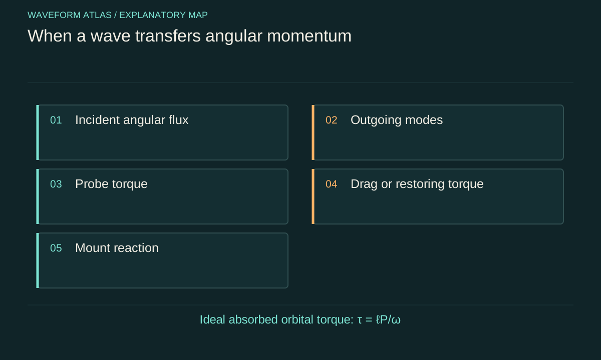
Begin with conservation of angular momentum
Torque is the rate of change of angular momentum, with external fluxes included for an open system. For a probe illuminated by a beam, the mechanical torque equals the appropriate difference between incoming and outgoing field angular-momentum flux, together with any change in stored field angular momentum. Supports, surrounding fluid and electromagnetic near fields can participate. The chosen axis and system boundary must be stated.
This relation is more general than the statement a twisted beam makes things spin. A beam can carry angular momentum through a transparent probe with little transfer if the outgoing field retains it. Conversely, a device can experience torque while transmitting most optical energy if it changes polarization or spatial mode. Measure or model the interaction rather than assigning torque solely from the incident beam label.
Convert a paraxial mode label into a flux
For a monochromatic paraxial orbital eigenmode with label ℓ, photon energy is ℏω and orbital angular momentum about the specified axis is ℓℏ. A power P corresponds to photon flux P/(ℏω), giving orbital angular-momentum flux ℓP/ω. This relation connects a mode description with a mechanical scale. It assumes a well-defined frequency, axis and mode rather than an arbitrary structured field.
If all of that orbital angular momentum is absorbed, the ideal torque is ℓP/ω. If only part is absorbed or the outgoing field changes mode, sum the actual incoming and outgoing contributions. Polarization can add a spin contribution in the appropriate paraxial description. A mixture of angular modes requires their weighted fluxes and, where relevant, correlations rather than a single integer attached to the entire beam.
Calculate an illustrative torque scale
At wavelength 1064 nanometres, angular frequency is approximately 1.770×10¹⁵ radians per second. For one milliwatt of power, P/ω is about 5.65×10^(−19) newton metre. An ideal fully absorbed ℓ=3 orbital mode would therefore supply torque about 1.70×10^(−18) newton metre. These are calculated scales under complete absorption and a pure-mode assumption, not observed torque values from a device.
The small magnitude explains why mechanical response and calibration matter. A probe with low drag can rotate appreciably under a small sustained torque, while a stiff suspension may show only a tiny angular deflection. The observed speed or angle cannot be compared across probes without their mechanical parameters. A numerical vortex label does not determine a universal rotation rate.
Polarization changes can also exert torque
Beth's primary experiment measured torque on a polarization-changing optical element. In an ideal paraxial example, reversing circular polarization changes spin projection by two units of ℏ per photon. The element can receive torque of magnitude 2P/ω even when most power is transmitted. The outgoing polarization carries the complementary change, preserving the complete angular-momentum balance.
This mechanism differs from orbital phase winding. A torque measurement with uncontrolled polarization cannot uniquely identify orbital transfer. Measure input and output polarization and hold it fixed when testing the sign of a spatial winding. Conversely, a polarization-torque experiment need not contain a vortex. The shared mechanical observable should motivate careful separation of contributions rather than erasing their distinct physical origins.
A primary vortex experiment supplies a specific example
He and colleagues reported that absorptive particles trapped in a phase-singular laser beam rotated, and that reversing the singularity sign reversed the rotation direction. The publisher abstract identifies angular-momentum transfer associated with the helical wavefront, including linearly polarized beams. This is direct evidence for a particular optical-mechanical interaction, not merely a theoretical possibility inferred from a spiral drawing.
Our account uses the verified abstract and does not reproduce the full apparatus or uncertainty analysis. The result should not be generalized into a claim that every dark-centred beam produces the same motion. Particle absorption, geometry, trapping and surrounding-medium drag matter. A new experiment must characterize those conditions and distinguish orbital transfer from other optical forces that can also move a particle.
Rotation rate includes the mechanical response
A simple rotational equation is I dΩ/dt=τ_opt−ζΩ−κθ, with moment of inertia I, drag coefficient ζ and torsional stiffness κ. Different regimes simplify it differently. A freely rotating overdamped probe can reach terminal speed Ω≈τ_opt/ζ. A suspended probe at static equilibrium can instead have angle θ≈τ_opt/κ. During transients, inertia and both other terms may matter.
Calibrate the relevant parameters independently or fit them using controlled mechanical tests. A change in rotation speed can result from temperature-dependent drag or altered trapping geometry even if optical torque is unchanged. Record the medium, pressure and probe position. Without that mechanical model, a speed-versus-power graph may demonstrate a response but cannot provide a reliable absolute angular-momentum transfer rate.
Scattering changes the outgoing ledger
A probe can scatter light into several directions and modes. The outgoing angular momentum about the chosen axis includes both spin and orbital contributions and may differ from a simple transmitted-beam estimate. A reflected or deflected beam can also exert torque through its momentum acting at a lever arm. Those effects are part of ordinary conservation, not corrections that can always be ignored.
Collect or model enough of the scattered field to support the intended inference. An absorption-only torque formula is inadequate when scattering dominates. Likewise, a probe displaced from the beam axis can experience orbital motion around that axis as well as spin about its own centre. Distinguish those motions experimentally. They involve different moments of inertia and can couple through the trap and surrounding fluid.
The support receives reaction torque
A phase element that changes angular mode can exchange torque with its mount, even when the element appears stationary. The mount can transmit that angular momentum to the laboratory structure. No visible rotation is required because a large supported system can accommodate a small change with negligible angular displacement. This is the rotational counterpart of a fixed mirror receiving momentum from reflected light.
Include the source and optical train when evaluating any claim of net torque or propulsion. Measuring only the illuminated probe omits the reactions elsewhere in the apparatus. A device that redirects or changes a wave cannot be assumed reactionless because its most obvious optical component does not move. The complete angular-momentum budget is the relevant test.
Mechanical work connects torque to energy
When a torque acts on a body rotating at angular speed Ω, the mechanical power transfer is τΩ. A stationary constrained element can receive torque while doing negligible mechanical work because Ω is nearly zero. A rotating element can exchange energy with the field, potentially accompanied by frequency changes in the outgoing light. Energy and angular momentum are related through the actual motion, not through an assumption that every torque requires large heating.
Track absorption separately from rotational work. Absorbed optical energy may predominantly become internal heat while only a small portion appears as mechanical motion. A high rotation speed does not imply efficient conversion of optical energy into useful work without knowing drag and torque. State the efficiency definition and include all input power when making such a comparison.
Use sign reversals and null controls
Reverse the intended orbital winding while holding power, radial profile and polarization as constant as possible. A corresponding reversal of calibrated torque is a useful discriminating test. Also use a no-winding control and reverse polarization independently. These comparisons help separate orbital and spin contributions from static misalignment or asymmetrical heating effects.
A rotating intensity pattern can drag or align a particle through mechanisms different from a stationary pure vortex mode. Compare the actual temporal field structure and test whether motion follows imposed pattern rotation. Monitor probe position and trap stability. The controls should target plausible alternative torques rather than treating any observed spinning as definitive evidence of the proposed angular-momentum channel.
Give the input and measured outgoing mode content, polarization, power and axis, together with the probe's inertia, drag or stiffness model. Report transient and steady behaviour separately and propagate calibration uncertainty into torque. Label theoretical flux calculations as calculations, and retain the distinction between a measured angular deflection and an inferred torque.
A well-supported conclusion identifies which angular momentum moved from which field channel to which mechanical component. That account can establish a remarkable optical control effect while remaining fully compatible with conservation. It also prevents the everyday notion of twist from obscuring whether the experiment involved polarization change, orbital mode transfer, lever-arm forces or a combination of them.
A static torsion calibration gives another scale check. If a suspension has stiffness 10^(−12) newton metre per radian, a torque of 10^(−18) newton metre produces an equilibrium deflection of 10^(−6) radian in the linear model. The angle becomes smaller if stiffness increases, even though the optical transfer is unchanged. This hypothetical calculation connects the flux estimate to an observable and shows why stiffness calibration belongs in the uncertainty budget. Background mechanical torques and drift must be resolved at the corresponding angular scale before assigning the deflection to the optical mode.
What to take forward
- Torque follows the complete angular-momentum flux balance.
- Rotation speed also depends on drag, inertia and restoring forces.
- Polarization and orbital transfer need separate controls.
Go to the original work.
These links identify the sources behind specific claims. Verification scope varies by source and is stated below.
- 1 / Primary theoryAllen et al. (1992), Orbital angular momentum of light and the transformation of Laguerre-Gaussian laser modes ↗
L. Allen; M. W. Beijersbergen; R. J. C. Spreeuw; J. P. Woerdman. Physical Review A 45, 8185 (1992).
Paraxial Laguerre–Gaussian modes can carry defined orbital angular momentum and be transformed between mode bases.
Verification scope: Publisher abstract and publication metadata inspected.
- 2 / Primary experimentBeth (1936), Mechanical Detection and Measurement of the Angular Momentum of Light ↗
Richard A. Beth. Physical Review 50, 115 (1936).
Torque from polarization changes, with sign and parameter dependence tested mechanically.
Verification scope: Publisher abstract and metadata inspected; full original uncertainty analysis not read.
- 3 / Primary experimentHe et al. (1995), Direct Observation of Transfer of Angular Momentum to Absorptive Particles from a Laser Beam with a Phase Singularity ↗
H. He; M. E. J. Friese; N. R. Heckenberg; H. Rubinsztein-Dunlop. Physical Review Letters 75, 826 (1995).
DOI: 10.1103/PhysRevLett.75.826
Absorptive particles rotated under a structured beam; the reported direction reversed with singularity sign.
Verification scope: Publisher abstract and publication metadata inspected; no quantitative performance extrapolation.
Found a problem with a claim or calculation? Send the page, the claim and the evidence. Read how these articles were prepared.