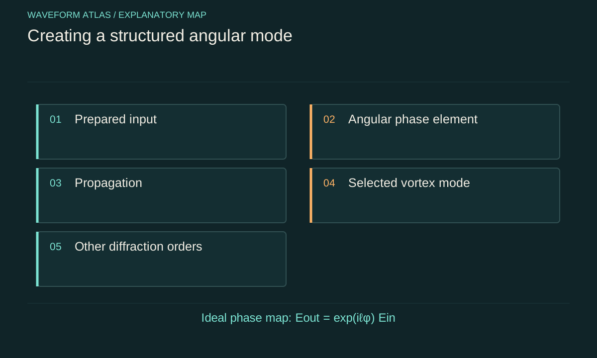
Specify the input field and target mode
A vortex generator transforms a prepared input into a desired output spatial state. Begin with the input amplitude, phase, polarization and wavelength. Then define the target: a winding number alone, a particular radial mode, or a coherent superposition of angular modes. These are different goals. A device can produce the desired phase winding while distributing power among several radial modes or unwanted diffraction orders.
The target should be normalized according to the comparison. For classical light, retain the actual optical power as well as a normalized shape. For a single-photon mode, preserve the probability of reaching the selected output. A beautiful normalized output image can conceal poor efficiency. Establishing the complete input-to-output transformation is more informative than showing only the most favourable transmitted region.
An ideal angular phase mask gives a simple map
In a scalar thin-element approximation, E_out(r,φ)=exp(iℓφ)E_in(r,φ). The multiplier has unit magnitude, so it preserves intensity at that plane away from the singular core and any physical imperfections. It changes phase, which affects diffraction and interference during later propagation. The map illustrates how spatial structure can be imposed without an immediate local amplitude reduction.
The central point requires care because azimuth is undefined at r=0. A real element has finite resolution and a finite physical core, and the propagated field develops the corresponding structure. Applying an ideal singular phase to an arbitrary nonzero on-axis input is a useful limiting construction, not a complete finite-energy device model at arbitrarily small scales. Specify the regularization and aperture in a numerical calculation.
Phase winding does not fix the radial mode
A fundamental Gaussian multiplied by exp(iℓφ) does not automatically become a pure Laguerre–Gaussian mode of the same waist. The target mode includes a particular radial amplitude as well as the angular phase. The phase-only product can therefore contain several radial components with the desired angular label. Their propagation can create different ring sizes and radial oscillations.
Measure overlap with the full target mode if mode purity matters. A camera ring and a winding measurement establish useful properties but do not determine every radial coefficient. An amplitude-and-phase design or a suitable mode-conversion sequence may be needed for a higher-purity target. Distinguish a generator of topological charge from a generator of one complete orthogonal mode; the latter is a stricter engineering objective.
A hologram often creates several output orders
A programmed or fabricated phase pattern can combine an angular phase with a carrier grating. The grating separates diffraction orders so that a desired order can be selected spatially. Other orders remain part of the output energy budget. An aperture that passes one order is a filter and reduces useful throughput, even if the selected field is well formed.
Calibrate the phase response at the actual wavelength and polarization. Pixelation, finite phase range and fabrication errors can distribute light into unwanted components. A nominal phase setting in software is not automatically the phase applied by the device. Measure the resulting field and total power rather than assigning perfect conversion from the design file alone. The source, optics and alignment determine the realized transformation.
Refractive and astigmatic conversion offer other routes
A spiral phase element changes optical path with azimuth, while an astigmatic mode converter can transform appropriate input mode combinations into angular modes. Allen and colleagues' primary theoretical work connected Laguerre–Gaussian angular momentum with transformations between spatial mode families. The verified abstract supports reversible mode-conversion ideas; it should not be cited as though that paper reported every later vortex-generation experiment.
Different generators trade alignment sensitivity, bandwidth, efficiency and accessible modes. The relevant comparison is based on the user's optical task, not a universal best method. An element designed at one wavelength can impose a different phase at another. A converter requiring a particular input mode will perform differently with an uncharacterized beam. Record those preparation and spectral conditions when reporting its output.
Propagation completes the transformation
After the element, the complex field evolves under the propagation operator. A phase-only change at one plane can create a dark core and ring structure farther away through interference. The location of the observation plane therefore matters. A near-field image and a far-field image can both be correct while displaying very different shapes from the same device.
Model the full complex field through the relevant optics and compare with measurements at known planes. Include aperture truncation and detector response. In a numerical simulation, enlarge the spatial window and refine the grid to check that the core and rings are not aliasing artefacts. Label calculated propagation images as models and avoid presenting a fabricated intensity map as if it were experimental evidence.
Angular momentum comes from an interaction
If an optical element changes the field's angular-momentum flux, the element and its support receive the complementary change. The device need not visibly rotate for that conservation law to apply. A rigid mount can transmit torque to a larger structure. The optical transformation is therefore not angular momentum created without reaction; it is an exchange within the complete apparatus.
For a monochromatic paraxial mode, a change Δℓ in orbital label corresponds ideally to angular-momentum flux change Δℓ P/ω where P is beam power and ω is the angular optical frequency, with input and output power and frequency appropriately accounted for. This simple relation assumes a well-defined mode and axis. Loss, polarization conversion and multiple outgoing orders require summing their contributions. The measured torque depends on that complete balance rather than only on the selected output label.
Nonlinear generation has additional bookkeeping
Dorney and colleagues reported control of polarization and vortex charge in high-harmonic beams through simultaneous spin–orbit momentum conservation. The verified NIST primary publication record describes theory and experiment in a nonlinear generation setting. It illustrates a different route from a passive thin phase mask: multiple driving fields and frequency conversion participate in the output structure.
For such a process, track energy and angular momentum across the pumps, generated harmonics and material response. A high-harmonic mode cannot be interpreted by simply multiplying one input by an arbitrary phase factor while ignoring the frequency change. The specific selection rules and geometry belong to the nonlinear model. Our reference to the experiment establishes its reported control mechanism, not a set of invented output efficiencies or harmonic spectra.
Quantify useful efficiency and purity separately
Useful efficiency is the power or detection probability reaching the intended output channel. Mode purity concerns the fraction of that output matching the target state under a specified decomposition. A highly pure selected mode can have low overall efficiency if most light was filtered away. Conversely, high transmission can coexist with substantial mode mixing. Report both quantities and their measurement definitions.
For a hypothetical one-watt input, suppose 0.7 watt reaches a selected order and 90 percent of that order overlaps the target mode. The target-mode power is 0.63 watt, or 63 percent of the input. These illustrative numbers are not device data. They show why quoting only 90-percent purity would not communicate the source-to-target efficiency. Also account for detector calibration and collection aperture when estimating either quantity.
Test the generated state with a reference
Measure the output intensity, interfere it with a known reference and project it into relevant angular and radial modes. Reverse the intended winding and check that the signed phase measurement responds accordingly. Vary alignment and wavelength within the operating range. These controls reveal whether a nominally correct setting remains robust or depends on a narrowly optimized condition.
A stable inverse transformation that recovers the original phase-sensitive field supports coherent mode conversion. It does not require that every photon be transmitted, so report losses separately. If the inverse fails, investigate mode mismatch, phase calibration and environmental fluctuations before concluding that the generator destroyed coherence. A changed spatial mode is expected from the device; the question is whether the information remains in controlled amplitudes and phases.
A clear diagram shows input preparation, the element's specified phase or coupling, propagation, selected and rejected outputs, and the measurement plane. It labels the ideal assumptions and the quantities actually measured. A spiral graphic without these connections can imply a physical mechanism that the apparatus does not implement.
The final result should identify the achieved winding, radial structure, polarization, useful efficiency and phase stability. Those properties make a generated vortex scientifically and practically useful. They also keep the operation distinct from material torsion, rigid rotation and quantum measurement. Creating angular structure can be a reversible change of mode, with losses and angular-momentum reaction treated as measurable parts of the implementation.
A simplified phase-quantization calculation estimates one source of imperfect mode conversion. If an ideal phase ramp is replaced by M equally spaced phase levels with uniform sampling and no other errors, the amplitude overlap with the intended ramp has magnitude sin(π/M)/(π/M). The squared overlap is approximately 0.9496 for eight levels and 0.8106 for four. These are calculated ideal overlap factors, not measured device efficiencies; finite aperture, pixel geometry, polarization and radial mismatch add other effects. The calculation is useful because it predicts a specific trend that can be separated from absorption by measuring unwanted output modes.
What to take forward
- An angular phase mask does not guarantee a pure radial mode.
- Useful efficiency and conditional mode purity are different metrics.
- The generating element receives the complementary angular-momentum reaction.
Go to the original work.
These links identify the sources behind specific claims. Verification scope varies by source and is stated below.
- 1 / Primary theoryAllen et al. (1992), Orbital angular momentum of light and the transformation of Laguerre-Gaussian laser modes ↗
L. Allen; M. W. Beijersbergen; R. J. C. Spreeuw; J. P. Woerdman. Physical Review A 45, 8185 (1992).
Paraxial Laguerre–Gaussian modes can carry defined orbital angular momentum and be transformed between mode bases.
Verification scope: Publisher abstract and publication metadata inspected.
- 2 / Primary experimentDorney et al., Controlling the polarization and vortex charge of attosecond high-harmonic beams via simultaneous spin–orbit momentum conservation ↗
Kevin Dorney et al.. Nature Photonics 13, 123–130 (2019).
DOI: 10.1038/s41566-018-0304-3
Theory and experiment demonstrate structured high-harmonic beams with spin and orbital angular momentum control.
Verification scope: NIST author record and Nature Photonics bibliographic metadata inspected: online 10 December 2018; volume 13 publication 2019. Full experimental analysis not audited.
- 3 / ReviewYao and Padgett, Orbital angular momentum: origins, behavior and applications ↗
Alison M. Yao; Miles J. Padgett. Advances in Optics and Photonics 3(2), 161–204 (2011).
Spin and orbital angular momentum; §2 generation by phase plates/diffractive elements; §6 angular-mode measurements.
Verification scope: Publisher metadata and introductory spin/orbital distinctions read directly. Contents identify generation sections 2.1–2.4; targeted measurement and reciprocal fork-hologram passages in sections 6.1–6.2 read through indexed author-repository PDF text after direct fetch timeouts. Entire review not read.
Found a problem with a claim or calculation? Send the page, the claim and the evidence. Read how these articles were prepared.