Start with the ambiguity in a ring image
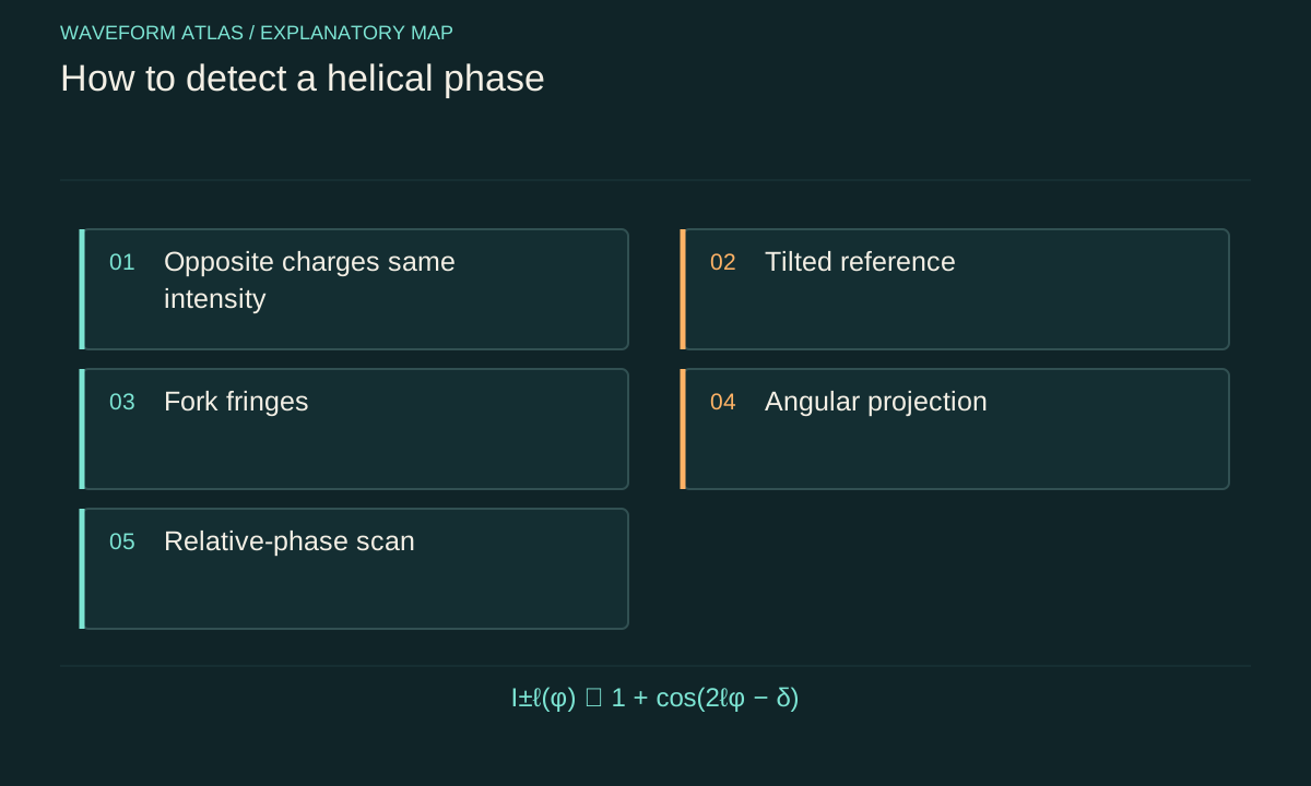
Fields with identical radial amplitude and angular factors exp(iℓφ) and exp(−iℓφ) have the same intensity. A field with no winding can also be shaped into an annulus. A camera measuring only intensity therefore cannot generally infer signed phase winding without additional assumptions. The missing information is a property of the measurement, not evidence that phase is physically meaningless.
Define the question before choosing a detector. Identifying a singularity, estimating its charge, measuring an angular-momentum spectrum and testing coherence between angular modes are related but different tasks. A method suitable for one may not resolve the others. State what the apparatus directly measures and which inferences rely on a restricted family of input fields.
Use interference to reveal relative phase
Combine the unknown field E with a known reference R. The measured intensity includes 2 Re(ER*), which depends on relative phase. This cross term converts phase variation into fringes. If the reference is stable and characterized, a sequence of phase-shifted measurements can reconstruct the unknown complex field over the reliable aperture. The reference's amplitude and phase uncertainty enter the reconstruction.
A single interferogram may suffice for some constrained patterns but can remain ambiguous in a general field. Record the reference geometry, polarization overlap and relative frequency. Orthogonal polarizations or unstable frequency differences can suppress the useful cross term. A missing fringe does not uniquely identify lost coherence until those measurement conditions have been checked.
Interpret a fork with its orientation
A vortex interfered with a tilted approximately plane reference can produce a forked fringe pattern near its phase singularity. The dislocation relates to phase winding, while the apparent handedness depends on reference tilt and coordinate conventions. Comparing the observed pattern with a calculated field model is safer than assigning a sign from a remembered picture.
The core can be off-centre, several singularities can lie within the image, and finite resolution can merge features. A bright or saturated region may obscure the fringe count. Use a calibrated field of known charge to establish the sign convention and resolution limits. Report whether the estimate concerns one isolated singularity or the net winding around a chosen loop enclosing several of them.
Reconstruct phase on a reliable loop
After complex-field reconstruction, choose a closed path that avoids amplitude zeros and poorly resolved regions. Unwrap the phase consistently around that path and sum its changes. The result should approach 2π times an integer for a well-resolved isolated winding in the assumed smooth field. The path choice is part of the analysis and should be reported.
Noise becomes particularly damaging near low amplitude because phase is then weakly determined. Repeating the winding estimate on several nearby loops can reveal instability or missed singularities. A phase jump caused by the display wrapping at ±π should not be counted as an independent physical discontinuity. Use the complex field or a careful unwrapping method rather than reading charge directly from colour boundaries.
Angular-mode projection measures a spectrum
At a fixed radius, angular dependence can be expanded in Fourier components exp(iℓφ). For a full beam, the radial structure must also be included in the mode basis. A calibrated projection onto a normalized mode u_j measures an amplitude proportional to the overlap integral ∫u_j*E dA in the ideal coherent model. A subsequent intensity measurement gives the squared magnitude of that amplitude.
The resulting mode populations can identify positive and negative angular components even when their direct intensity profiles agree. However, populations alone do not determine relative phases between components. A complete state description requires additional superposition-basis measurements when those phases matter. A sorter that reports one integer per detection is measuring an angular basis, not simultaneously reconstructing every coherent relation in the input.
Radial mismatch can look like absent angular content
Two modes can share the same winding number but have different radial profiles. A receiver matched to one radial mode may reject another, producing a weak signal despite the correct angular phase. A single-mode fibre after a phase-flattening element is sensitive to both angular correction and radial overlap. Its transmission is therefore not automatically a pure measurement of topological charge.
Calibrate the response matrix using known input modes spanning the expected radial and angular range. Include cross-talk and efficiency in the inference. If the basis is incomplete, state which modes remain unmeasured. A reduction in one projection channel can mean redistribution among unobserved modes rather than loss of total power or coherence. An independent wide-aperture power measurement helps resolve that ambiguity.
Superposition patterns reveal relative phase
For equal radial envelopes, an equal coherent superposition of +ℓ and −ℓ gives an angular intensity proportional to 1+cos(2ℓφ−δ), where δ is their relative phase under the chosen convention. There are 2|ℓ| lobes for nonzero integer ℓ. Changing δ rotates the pattern by δ/(2ℓ), with sign determined by conventions. An incoherent equal mixture lacks this interference term.
For ℓ=2, the ideal pattern has four lobes. A relative phase change of π/2 rotates it by π/8, or 22.5 degrees. These are calculated examples, not measured images. The relation assumes matching radial profiles and polarization. Unequal amplitudes reduce visibility, while phase fluctuations blur the lobes in an averaged image. Those effects should be included before using a pattern as a coherence witness.
Separate individual trials from averaged images
A coherent angular superposition can have a different relative phase on each trial because of technical drift. Individual images may show high-contrast lobes whose orientation varies, while the average becomes a smooth ring. That average is not evidence that each realization lacked structure. Record a phase reference or analyse individual trials when the protocol permits it.
Averaging and postselection should be disclosed. Aligning patterns after looking at the data can introduce bias, especially near the noise floor. Test the alignment procedure on controls with known phase statistics. The meaningful conclusion concerns the coherence relative to the available reference and measurement record, not a visually preferred average assembled without accounting for the processing.
Polarization must be measured independently
A structured beam can have spatially varying polarization as well as phase. A scalar reconstruction based on one analyser may characterize only one polarization component. Another component can contain a different winding or fill the apparent dark core. Report the analyser setting and, where necessary, reconstruct both components or their polarization correlations.
This is particularly important when a device couples spin and orbital degrees of freedom. Tracing over polarization can hide spatial coherence that reappears after a conditional polarization projection. The appropriate experiment depends on whether the claim concerns the complete vector field or a selected component. A scalar ring image cannot settle both questions without additional measurements.
Calibrate the complete detector response
Verify camera linearity, background, spatial resolution and pixel geometry. Saturation can reshape bright rings, while smoothing can merge narrow fringes or singularities. Correct lens distortion and establish the beam axis using an independent alignment procedure where possible. An off-axis analysis origin can mix angular components and change the inferred spectrum.
Use several known charges and a no-winding control to characterize the analysis, including false assignments. Repeat at relevant power levels and exposure times. A method that succeeds only on its own ideal simulated patterns has not been validated for experimental noise and aberrations. Keep calculated reference images distinct from observations and provide enough calibration information for the uncertainty estimate to be assessed.
A clear result might identify a signed winding around a specified loop, an angular population distribution over a stated mode set, or a measured phase relation between two alternatives. Include radial assumptions, polarization, axis, throughput and uncertainty. These statements tell the reader what was learned and what remains unmeasured.
The same measurements can diagnose a twisting device: unchanged total power with redistributed angular populations suggests mode conversion, while stable superposition fringes demonstrate accessible phase relations. Loss of one projected signal alone does neither. A helical-phase measurement becomes persuasive when it resolves alternatives that share the same intensity image, rather than treating the appearance of a doughnut as the end of the analysis.
A four-step reference measurement illustrates phase recovery. Let the reference phase take values zero, π/2, π and 3π/2 while the unknown field stays fixed. Then I₀−Iπ gives four times the real part of ER*, and Iπ/₂−I₃π/₂ gives four times its imaginary part under the stated reference convention. Knowing R therefore permits reconstruction of E wherever the reference is nonzero and the detector is linear. This calculation assumes identical field amplitude during all four exposures. Drift, motion or saturation breaks that assumption and can create false phase structure. Interleave reference checks and quantify those errors rather than treating a reconstructed colour map as direct noiseless evidence.
Repeat the reconstruction with a known reference mode to verify the sign and scale of the recovered complex field.
What to take forward
- Intensity alone generally cannot identify signed winding.
- Reference interference and calibrated projections reveal complementary information.
- Population imbalance and radial mismatch can reduce contrast without destroying a pure state.
Go to the original work.
These links identify the sources behind specific claims. Verification scope varies by source and is stated below.
- 1 / Primary theoryAllen et al. (1992), Orbital angular momentum of light and the transformation of Laguerre-Gaussian laser modes ↗
L. Allen; M. W. Beijersbergen; R. J. C. Spreeuw; J. P. Woerdman. Physical Review A 45, 8185 (1992).
Paraxial Laguerre–Gaussian modes can carry defined orbital angular momentum and be transformed between mode bases.
Verification scope: Publisher abstract and publication metadata inspected.
- 2 / ReviewYao and Padgett, Orbital angular momentum: origins, behavior and applications ↗
Alison M. Yao; Miles J. Padgett. Advances in Optics and Photonics 3(2), 161–204 (2011).
Spin and orbital angular momentum; §2 generation by phase plates/diffractive elements; §6 angular-mode measurements.
Verification scope: Publisher metadata and introductory spin/orbital distinctions read directly. Contents identify generation sections 2.1–2.4; targeted measurement and reciprocal fork-hologram passages in sections 6.1–6.2 read through indexed author-repository PDF text after direct fetch timeouts. Entire review not read.
- 3 / Primary experimentLeach et al., Measuring the orbital angular momentum of a single photon ↗
J. Leach; M. J. Padgett; S. M. Barnett; S. Franke-Arnold; J. Courtial. Physical Review Letters 88(25), 257901 (2002).
DOI: 10.1103/PhysRevLett.88.257901
Interferometric angular-momentum measurement and demonstrated sorting of four states; not a universal phase-reconstruction protocol.
Verification scope: Author-institution record and primary abstract inspected; full experiment and uncertainty analysis not read.
Found a problem with a claim or calculation? Send the page, the claim and the evidence. Read how these articles were prepared.