The generated field is a sum over positions
A nonlinear medium can act as a distributed source for a new optical frequency. Each small region generates a contribution that propagates to the output. The final amplitude is the coherent sum of those contributions, including their phases. Strong local generation can still yield weak net output if contributions from different positions arrive out of phase.
This is a wave-addition problem within a physical energy-transfer process. It should not be described as energy becoming nothing when the output is small. Under mismatch, energy transfer can be suppressed or can reverse among the interacting fields in a fuller coupled model. The original pump and signal remain part of the budget. Phase matching therefore addresses efficient accumulation, not whether the frequency relation is energetically allowed. Both requirements matter, and satisfying one does not automatically satisfy the other.
Define mismatch for the chosen interaction
For collinear sum-frequency generation, a common definition is Δk = kout−k1−k2, with each wave number evaluated at its own frequency, polarization, and mode. The energy relation is ωout = ω1+ω2. Because refractive index depends on frequency and polarization, the energy relation does not generally force Δk to vanish.
For second-harmonic generation, the corresponding form is Δk = k2ω−2kω. For difference-frequency or four-wave processes, signs and participating wave vectors change. Noncollinear geometries require a vector relation rather than one scalar wave number. State the convention before using a mismatch value, especially when comparing formulas from different sources. A periodic structure can add a reciprocal spatial wave vector, changing the effective mismatch. The physical question remains whether the nonlinear source phase tracks the generated mode closely enough over the device length.
Integrating the phasors produces the sinc response
Assume uniform coupling, undepleted driving fields, negligible loss, and constant mismatch. The generated amplitude is proportional to A(L) = C∫0L exp(iΔkz)dz. Evaluating the integral gives CL exp(iΔkL/2)sinc(ΔkL/2), where sinc(x) = sin(x)/x and sinc(0)=1.
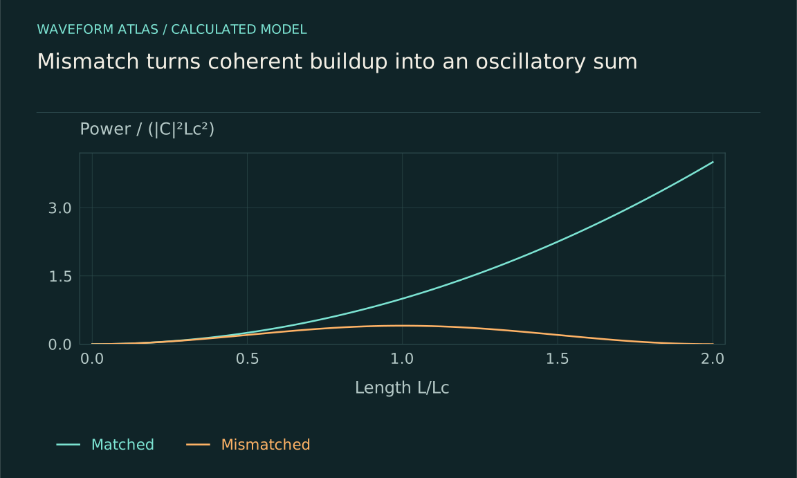
The generated power is therefore proportional to |C|²L²sinc²(ΔkL/2). At perfect matching, amplitude grows linearly with length and power quadratically within the approximation. At nonzero mismatch, the phasors turn as contributions accumulate, reducing the final sum. This derivation is an original worked model using the standard phase-matching framework. It is not a universal high-conversion law: depletion, focusing, absorption, spatial walk-off, and changing coupling can alter the length dependence. The explicit assumptions explain when the familiar sinc curve is an appropriate prediction to fit.
Coherence length here means a phase-slip scale
Define the nonlinear phase-matching coherence length as Lc = π/|Δk|. Over that distance, the relative phase slips by π. In the simple integral model, the first generated-power maximum versus length occurs at Lc, while the first return to zero occurs at 2Lc. This convention should be stated because the word coherence length is also used for a source's temporal phase correlation.
For an illustrative mismatch of 1,000 inverse meters, Lc is about 3.14 millimeters and the first zero occurs near 6.28 millimeters. A 1-millimeter device has ΔkL/2 = 0.5 and a mismatch factor sinc²(0.5) ≈ 0.919 relative to the perfectly matched output at that same length. These calculated values show how device length and mismatch combine. A source can remain highly coherent while its generated contributions accumulate an unfavorable deterministic phase.
Longer devices narrow the matching tolerance
The sinc-squared factor depends on the product ΔkL. A longer interaction can produce more output near perfect matching, but a smaller change in mismatch then moves the device away from its optimum. If mismatch varies approximately linearly with wavelength, temperature, or angle near the operating point, the useful acceptance range typically shrinks as length grows in this simple regime.
The precise bandwidth depends on which parameter is varied and how all participating frequencies respond. A fixed pump with a varying signal is not the same tuning experiment as varying the pump and signal together. State whether bandwidth means full width at half maximum, a specified efficiency tolerance, or another criterion. A broad input pulse can sample a range of mismatches and emerge with spectral filtering or distortion. High peak conversion at one wavelength is therefore not sufficient evidence of broadband conversion fidelity.
The same model gives a numerical acceptance width. The central sinc-squared response falls to half its peak when |Δk|L/2 is approximately 1.3916. Its full width at half maximum in mismatch is therefore approximately 5.566/L. For L = 10 mm, this is about 557 m⁻¹. Translating that into a temperature or wavelength width requires the actual derivative of mismatch with respect to that control; the length alone does not supply a universal thermal or spectral tolerance.
Quasi-phase matching changes the coupling pattern
A periodically structured nonlinear medium can reverse or modulate the effective nonlinear coefficient so that contributions that would otherwise oppose the accumulated field instead reinforce it on average. In a first-order description, a grating period Λ supplies spatial wave vector 2π/Λ, giving Δkeff = Δk−2π/Λ for the chosen sign and order.
If the original mismatch is 1,000 inverse meters, a first-order period near 6.28 millimeters would compensate it in this illustrative model, with sign reversals every half period for a symmetric square pattern. Real optical periods are determined by actual dispersion and geometry, not this arbitrary example. Quasi-phase matching can access useful nonlinear tensor components and engineered tuning curves, but fabrication errors and domain structure affect efficiency. Fejer and colleagues' primary analysis treats these tolerances, making clear that periodicity is a designed part of the interaction rather than a guarantee of perfect conversion.
Birefringence and geometry offer other matching controls
Different polarizations in an anisotropic crystal can experience different refractive indices. Choosing propagation direction and polarization can therefore bring the relevant wave-vector relation closer to matching. Waveguide confinement changes propagation constants and can provide another degree of freedom. Temperature shifts refractive indices and can tune the operating point.
Each control has tradeoffs. Angular tuning can change beam overlap or spatial walk-off; temperature tuning can change absorption and alignment; waveguide designs can introduce fabrication sensitivity and coupling loss. A measured conversion peak during a scan should be compared with a model that includes these effects where they matter. The strongest evidence for phase matching is a consistent dependence on several controlled parameters, not simply a brighter output after one adjustment. Independently measured material or mode properties reduce the freedom to explain any curve after the fact.
Group-velocity matching is a separate pulse condition
Phase matching concerns carrier phases, while group velocities govern how pulse envelopes overlap. A device can be phase matched at central frequencies yet allow pump and signal pulses to walk apart. The effective interaction length can then be limited by the pulse duration divided by their relative inverse-group-velocity difference.
For an illustrative relative delay of 100 femtoseconds per millimeter and a useful overlap duration of 500 femtoseconds, a rough walk-off length is 5 millimeters. The exact conversion depends on pulse shapes, chirp, and which group velocities participate. This estimate is a design scale, not an efficiency prediction. Spectral phase matching and temporal overlap must be considered together for short pulses. A continuous-wave tuning curve can be an incomplete guide to pulsed performance, especially when a longer crystal increases both nominal nonlinear buildup and envelope separation.
Measure a tuning curve with a complete baseline
Scan a controlled parameter such as temperature, angle, or input wavelength while monitoring input and pump powers. Record desired output, residual input, and background. Compare the normalized response with a model using the correct mismatch convention and device length. Repeat at a weaker input or pump level to test whether depletion or heating changes the curve.
A phase-matching peak can be broadened or distorted by inhomogeneous temperature, fabrication variation, finite beam divergence, and detector bandwidth. Pump-only measurements distinguish generated background from converted signal. A fitted sinc shape is useful evidence but does not uniquely establish every microscopic parameter. Report uncertainty and the operating range over which the simple model works. If the response differs, use the deviation to identify additional physics rather than forcing the curve to match by changing an undefined effective length.
Mismatch suppresses transfer, not conservation
When phase matching is poor, the desired output can remain weak even in a strongly nonlinear material. The energy may remain in the input fields, exchange back among modes, or enter ordinary loss channels. A small converted signal is not evidence that the generated field or pump energy vanished into an undefined state.
The useful design task is to align energy-frequency relations, spatial phase accumulation, mode overlap, and pulse timing over the intended operating range. The simple phasor integral gives a transparent baseline, and more complete coupled equations handle depletion and other effects. With its assumptions stated, phase matching explains why a longer device sometimes helps and sometimes cancels its own net buildup. It connects a measurable tuning curve to a concrete mechanism without confusing deterministic phase slip with decoherence or fundamental collapse.
What to take forward
- Frequency balance and phase matching are distinct requirements.
- The undepleted uniform model gives L²sinc²(ΔkL/2) power scaling.
- Long interaction improves matched buildup but narrows tolerance and can increase pulse walk-off.
Go to the original work.
These links identify the sources behind specific claims. Verification scope varies by source and is stated below.
- 1 / Primary theoryQuasi-phase-matched second harmonic generation: tuning and tolerances ↗
M. M. Fejer, G. A. Magel, D. H. Jundt, and R. L. Byer. IEEE Journal of Quantum Electronics 28(11), 2631–2654 (1992).
Phase mismatch, coherence length and periodic sign reversal of nonlinear coupling
Verification scope: Author-hosted original paper text inspected in the introduction and relevant phase-matching discussion; published bibliographic record verified. This is the 1992 tuning-and-tolerances analysis, not the origin of quasi-phase matching.
- 2 / University teachingFundamentals of Photonics: Quantum Electronics — lecture notes ↗
Franz X. Kärtner. Fundamentals of Photonics: Quantum Electronics — lecture notes. 2006.
Population dynamics, absorption/gain, Rabi oscillations and coupled modes
Verification scope: Official author-written course materials and topic mapping inspected
- 3 / University teachingUltrafast Optics — lecture notes ↗
Franz X. Kärtner. MIT Ultrafast Optics: Lecture Notes. 2005.
Pulse amplification and ultrafast optical dynamics
Verification scope: Official course material records inspected
- 4 / University teachingFranz Kärtner — Classical Electromagnetism and Optics, chapter 2 ↗
Coupled-mode equations, power normalization, polarization and waveplate transformations
Verification scope: Official author PDF selected sections 2.7 and 2.9 equations inspected; not all 159 pages read
- 5 / University teachingQuantum Optical Communication — Jeffrey H. Shapiro, readings and lecture slides ↗
Jeffrey H. Shapiro. Quantum Optical Communication — Jeffrey H. Shapiro, readings and lecture slides. 2016.
Author-written quantum attenuator, amplifier, detection and parametric interaction framework
Verification scope: Official course materials and topic mapping inspected
- 6 / University teaching6.453 Quantum Optical Communication: Reading 20 ↗
Jeffrey H. Shapiro (2016). 6.453 Quantum Optical Communication, Reading 20: Nonlinear Optics of χ² Interactions. MIT OpenCourseWare.
Second-order nonlinear polarization, three-wave coupled equations, photon-flux normalization, phase matching and pump-to-pair energy relations.
Verification scope: Official lecture PDF inspected in the nonlinear constitutive-relation, coupled-mode and phase-matching passages, pp. 5–10. The lecture’s strong high-frequency pump describes parametric downconversion; one-to-one frequency conversion is separately supported by Armstrong and the cited conversion experiments.
- 7 / Primary theoryInteractions between Light Waves in a Nonlinear Dielectric ↗
J. A. Armstrong, N. Bloembergen, J. Ducuing, and P. S. Pershan. Physical Review 127(6), 1918–1939 (1962).
Nonlinear three-wave coupling, energy relations, and the 1962 proposal to correct phase repeatedly by reversing crystal orientation.
Verification scope: APS original paper inspected at the abstract and the phase-correction discussion, pp. 1935–1936. The historical statement is limited to priority over the 1992 analysis; no priority claim relative to birefringent phase matching is made.
Found a problem with a claim or calculation? Send the page, the claim and the evidence. Read how these articles were prepared.